This tutorial will deal with how to design columns and walls in Orion 18.
In this tutorial, we learn both to design columns in batch as well as interactively (when the columns or walls fail). We will also learn how to deal with the different failures that occur during the column design, view the interaction diagram of the column and print out our design reports.
And for those who have followed us from the beginning of the series, we also get to use our generate functionality in the structure.
Now, let’s begin
Step 1
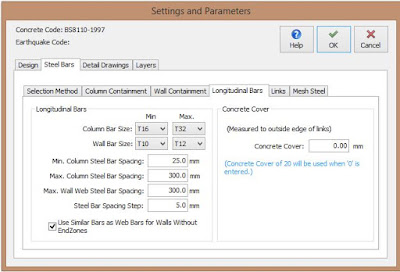
Before the actual designing starts, we will make a few adjustments to the settings to be used for the design. Click on ‘Settings’, then ‘Column Design Settings’ on the menu bar at the top of the screen. Click on the ‘Steel Bars’ tab, then on ‘Longitudinal Bars’. Input the settings as shown below.
Step 2
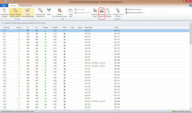
Click ‘Run’, then ‘Column Section Design’. In the dialog box that appears, click ‘Column Design (Batch Mode)’ to begin batch design.
Step 3
From the Batch Design, we can see that some columns have failed. Now, we will proceed to design them interactively using ‘1C4’ as an example. This same procedure can also be used for others.
Double click ‘1C4’. Click on ‘Interactive Design’. The ‘Column Reinforcement Design’ dialog box appears as shown below.
Here, we can see that the ratio of steel provided to cross sectional area of concrete (steel limit ratio) exceeds what is stipulated in the code (Ast/Ac = 0.6). Therefore, we will increase the size of the column so that the ratio falls back below 0.6.
Step 4
To increase the cross sectional area.
- Close the ‘Reinforcement Design’ dialog box. Left click, then right click on the column (1C4) in the structure tree view on the left side of the screen. Select ‘Properties’
- Change ‘b1’ and ‘b2’ to 350. In the boxes, ‘e1’ and ‘e2’, fill 175 so that the column the column centre aligns with its axis line in both directions. Click ‘Update’
- Carry out the building analysis again for the whole building, then column design as we did earlier. We can see that the column design passed this time
BUT
If you check, you will see that the size of columns ‘2C4’ ‘3C4’ and ‘4C4’ also have their cross sections changed to 350. To change it back to 300 (without affecting the redesigned column)
- Generate the storeys as we showed in the earlier tutorial
- Left click, then right click on the column (2C4) in the structure tree view on the left side of the screen. Select ‘Properties’ and change its ‘b1’ and ‘b2’ to 300. Repeat the procedure for ‘3C4’ and ‘4C4’.
NB There are two main ways by which the columns fail.
- Failure due to required steel being greater than code recommendation (Ast/Ac > 0.06): This is the type we dealt with above.
- Failure due to “shear” (Links): This occurs when ‘Fail’ is indicated under the ‘Links’ column. If this happens, it will be because shear was not designed for by the software. Do this interactively by double clicking on the column, Click on ‘Shear Design’, then click on ‘Calculate’.
Step 5
To view the interaction diagram for the column, Click on ‘Column Analysis’ in the ‘Column Reinforcement Design’ dialog box still open.
To print the design report, Click ‘Design Report’ in the dialog box shown below.
For comments and questions, you can reach us through the contact form below. You can also subscribe to receive our weekly newsletters so that you never miss a thing.
ORION 18: HOW TO DESIGN COLUMN
 Reviewed by Izuchukwu Obi
on
19:48:00
Rating:
 Reviewed by Izuchukwu Obi
on
19:48:00
Rating:


No comments: